
Automotive Assembly Capture / Original EGO R10 guide; BMW Group automotive assembly reference / Sep 28, 2026
EGO R10 for Automotive Component Assembly Capture
Record automotive component assembly with EGO R10: synchronized views, 1600 × 1200 at 30 fps, HDR imaging and configured IMU data for human workflow review.
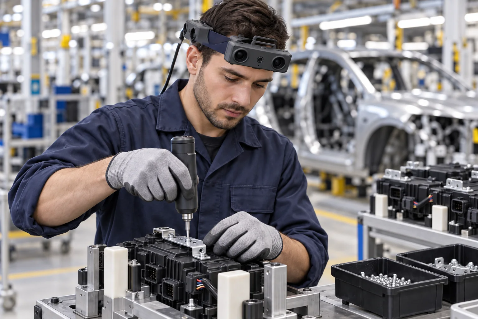
How can R10 record automotive component assembly?
- The proposed workflow records manual component positioning and fastening, with assembly specialists selecting and labeling the footage.
- R10 specifies 1600 × 1200 at 30 fps and synchronizes all cameras to a common hardware trigger or shutter signal.
- Fixed-focus views and documented linear/HDR modes form part of the assembly-station capture setup.
- USB 2.0, external DC 5 V power and configured 100 / 200 / 500 Hz IMU sampling can be included in the recording plan.
Review EGO R10 specifications and the supplied parameter tables
An automotive assembly recording is most useful when reviewers can follow the component, the operator’s hands and the transition between work steps. EGO R10 brings synchronized camera viewpoints to that recording task through a wearable multi-camera headband. This guide proposes an R10 capture workflow for manual automotive component assembly, from presenting a part to completing the visible fastening sequence, using documented assembly practices and the supplied R10 specifications.
A documented automotive assembly setting
BMW Group’s September 2025 description of assembly at Plant Debrecen discusses grouping small parts into modules, using plugs, screws and clips, and installing components at height-adjustable workspaces. These documented operations provide the application context for this recording plan. The proposed R10 project focuses on the human actions around a component and its connections, with the assembly team choosing the operation and its applicable work instruction.
Define the component and the recorded operation
Start with one component variant and one defined assembly station. In the session notes, record the component identifier, work-instruction revision, workstation and recording identifier. Select a short operation that the assembly team wants to document. For a module secured with a bracket, the planned footage could cover presenting the module, positioning the bracket, placing the tool at the specified fastening points and setting the assembly aside. The team’s own instruction determines the actual sequence.
Frame the hands, fixture and component supply
Before collecting a full operation, have the wearer perform the selected movements in the normal working position. R10 specifies fixed-focus imaging with a horizontal field of view of 115° and a vertical field of view of 80°. Review sample footage while the operator reaches toward the component supply, faces the fixture and brings the tool into the work area. Select the wearing position and useful camera views from these samples, keeping the relevant hands and assembly area in frame.
Record the visible assembly sequence at 30 fps
R10’s specified image resolution is 1600 × 1200 at 30 fps. Use the initial recording to examine the visible sequence around part placement and tool engagement at the station’s actual working distance. Keep the original recordings available alongside any short excerpts. When preparing clips for an assembly review, identify the camera and frame interval so the team can return to the complete operation and inspect the moments before and after each selected action.
Review corresponding camera viewpoints
All R10 cameras are synchronized to a common hardware trigger or shutter signal. This provides the hardware basis for corresponding views of the same assembly moment. For example, one selected view might contain the component in the fixture while another includes the nearby component supply as the wearer turns. Preserve the camera identities and synchronized recordings together; the assembly reviewer can choose the view that actually contains the hand movement or workstation detail being discussed.
Set imaging modes for the assembly station
The supplied R10 imaging table lists 61.56 dB dynamic range in linear mode and 91.56 dB in HDR mode, together with automatic exposure and white-balance controls. At an assembly station with dark module housings and brighter metal brackets, review a sample under the lighting used for the operation. Record the chosen image mode and settings with the session. This gives the team a clear record of the capture configuration when it later reviews the component’s appearance in the video.
Include motion data from the configured unit
For configurations that include the specified 6-axis IMU in the head or wrist units where required, R10 offers sampling rates of 100, 200 or 500 Hz. An assembly recording project using a configured head-unit IMU can retain the inertial data alongside the video under the same session identifier. Record the selected sampling rate and unit location. This preserves the motion measurements associated with the worn unit as the operator turns between the parts supply and the assembly position.
Prepare the recording connection and power
R10 provides USB 2.0 and lists MJPG, H.264 and H.265 output formats. Prepare the capture connection and review a sample in the project’s chosen playback workflow before recording the selected assembly sequence. Power comes from an external battery; the specified supply is DC 5 V, with a maximum working current of 320 mA. Arrange the cable and external power placement around the operator’s normal reach and keep the selected recording configuration in the session log.
Label the assembly steps with a specialist
After capture, an assembly specialist can label the visible intervals by hand: component presented, part positioned, tool applied and assembly set aside. Associate each interval with the component identifier, camera view and relevant work-instruction step. If a hand changes position or the wearer turns during a step, examine the corresponding R10 views and choose the footage that shows the action clearly. These human annotations organize the recorded operation for instruction review and discussion of the handling sequence.
Plan a focused R10 assembly recording pilot
A practical R10 assembly pilot should produce one complete sample sequence, the original synchronized camera files, a capture-settings record and the assembly specialist’s selected clips. Include configured IMU recordings when they are part of the project. Review this material with the people who perform the operation, then agree which views and steps to retain in further collection. Share the component type, station arrangement and desired R10 recording configuration with the EGO team when planning sample hardware.
Application reference and R10 specifications
BMW Group — Plant Debrecen, Assembly (17 September 2025, pages 16–17)
Review EGO R10 specifications and the supplied parameter tables