
Scaffold Assembly Research / Scaffolding activity research and EGO R8 field guide / Nov 10, 2026
Visual Inertial Data Collection: Scaffold Assembly with R8
Plan visual inertial data collection for scaffold assembly with EGO R8: synchronized stereo, selectable IMU rates and time-linked connection-event annotations.
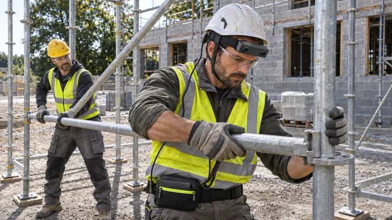
How can R8 support visual inertial data collection for scaffold assembly?
- Capture the visible connection operation with R8 dual global-shutter cameras and a common hardware trigger.
- Retain the selected 100, 200 or 500 Hz 6-axis IMU record with the stereo images and unified timestamps.
- Organize researcher-written event annotations by scaffold bay, connection point and recorded time interval.
Visual inertial data collection during scaffold assembly needs a clear record of both the connection being handled and the changing viewpoint of the worker. EGO R8 combines dual global-shutter stereo cameras with a 6-axis IMU and unified timestamps. A research team can use those records to study a worker positioning a scaffold member, working at a joint and turning toward the next component within one scaffold bay.
Study the transitions around one scaffold bay
Published scaffolding workface research separates erection, transport and waiting, and examines transitions between activities. For an R8 collection, that research provides a useful starting point: preserve the changes between handling a component and working at a connection, then let reviewers describe the visible events. The workflow here is a proposed R8 data-collection plan for scaffold assembly, with a single bay and its connection points as the unit of organization.
Define a bay identifier and give the relevant connection points simple labels before collection. A ground-level assembly session can include bringing a member into the work area, holding it near a joint, completing the visible connection operation and moving attention to the following member. Keep the task description tied to the scaffold system and components actually used in the session.
Record the complete interval around a connection rather than selecting only the moment of tool contact. The approach shows which member is being handled; the positioning interval shows the hands and joint; the release and following head turn show when attention changes to the next part of the bay. Preserve these intervals together so an annotator can interpret each action in its immediate construction context.
Pair the joint views with head-motion data
R8 uses two global-shutter cameras synchronized by a common hardware trigger or shutter signal. Keep the left and right image records paired when reviewing a hand moving a horizontal member toward an upright or a tool contacting a connector. The synchronized stereo record provides corresponding views of the visible joint at the same capture instant.
The integrated R8 6-axis IMU offers selectable 100, 200 or 500 Hz sampling. Record the selected rate with each scaffold session and retain the IMU samples alongside the stereo images. R8 unified timestamps provide the time reference for relating the head-mounted inertial record to the image sequence while the worker looks down at a joint, follows a member or turns toward a colleague.
During a short framing check, have the worker adopt the actual working postures used at that bay. Review whether both hands, the member end and the connector are visible during positioning and tool contact. A view directed toward the joint is useful for examining the operation; a subsequent turn provides visual context for the next component. Keep those viewpoint changes in the original recording.
Annotate the visible connection events
Annotators can mark visible events such as member entering the work area, first joint contact, tool contact, hands released and attention shifted. Attach a bay ID, connection ID and time interval to each label. These event descriptions are prepared by the research team from the R8 recording, while the original paired images and inertial samples remain the collection source.
When several connections appear in a take, identify the joint currently being handled instead of assigning one assembly label to the entire sequence. Retain any return to an earlier connection as part of the recorded order. A reviewer can then distinguish a new connection interval from a continuation at the same joint without losing the surrounding head movement and visual context.
Retain the R8 configuration with each bay
R8 per-unit calibration information includes camera intrinsics, distortion coefficients and stereo extrinsics where applicable. Keep the applicable calibration files associated with the device and selected capture configuration. For scaffold imagery containing repeated uprights, crossbars and similar-looking joints, preserving those identifiers makes the original stereo records traceable when the research team revisits a connection interval.
Plan the recording arrangement around the documented R8 USB 2.0 interface and DC 5 V supply. Keep the connection and external capture arrangement consistent with the demonstrated movements and retain the device and configuration identifiers with the session. The documented provision of an R8 SDK/API can support integration with the research team's recording software; the team organizes the resulting files and annotations by scaffold bay and connection event.
Review a complete connection interval
At review, locate the beginning and end of each selected connection interval in both image records, then use the recorded timestamps to find the corresponding IMU samples. Check the labelled joint against the original video and retain the complete take with any extracted segments. The resulting visual-inertial research material connects scaffold components, visible hand actions and the wearer's changing viewpoint in one time-indexed collection.
How should a scaffold capture session be organized?
Start with a clearly identified scaffold bay, its connection points and the work sequence being recorded. R8 synchronized stereo images show the visible handling operation, while its IMU and unified timestamps preserve the associated head-motion record. The researcher adds the event labels used to organize the collection.
Which R8 settings belong with the data?
The relevant R8 settings are the selected 100, 200 or 500 Hz IMU rate, the stereo capture configuration and the associated per-unit calibration files. Record them with the device identifier and preserve the unified timestamps when organizing each connection interval.
How can the team relate labels to the R8 recordings?
Use the paired R8 images to review when a member approaches a joint, when visible contact occurs and when the hands leave the work area. Link the researcher's labels to those intervals using the recorded time reference. This keeps visual inertial data collection focused on the scaffold operation being studied.
Research source and R8 product information
Scaffolding activity analysis: Ying et al., Applied Sciences (2021)